
一、Implement Steps
1.1 Matrix Calculation
- Calculate mass matrix M(1)
- Calculate the stiffness matrix of each suspension k(2)
- Calculate angle transpose matrix T(4)
- Calculate position transition matrix B(3)
- Accumulative calculation of stiffness matrix K(5)
M=\begin{bmatrix}
m&0&0&0&0&0\\
0&m&0&0&0&0\\
0&0&m&0&0&0\\
0&0&0&I_{xx}&-I_{xy}&-I_{xz}\\
0&0&0&-I_{xy}&I_{yy}&-I_{yz}\\
0&0&0&-I_{xz}&-I_{yz}&I_{zz}\\
\end{bmatrix}\tag{1}
k_i=\begin{bmatrix}
k_{ui}&0&0\\
0&k_{vi}&0\\
0&0&k_{wi}\\
\end{bmatrix}\tag{2}
B_i=\begin{bmatrix}
1&0&0&0&Z_i&-Y_i\\
0&1&0&-Z_i&0&X_i\\
0&0&1&Y_i&-X_i&0\\
\end{bmatrix}\tag{3}T_i=\begin{bmatrix}
cos\alpha_{ui}&cos\beta_{ui}&cos\gamma_{ui}\\
cos\alpha_{vi}&cos\beta_{vi}&cos\gamma_{vi}\\
cos\alpha_{wi}&cos\beta_{wi}&cos\gamma_{wi}\\
\end{bmatrix}\tag{4}K=\sum_{i=1}^nB_i^\mathrm{T}T_i^\mathrm{T}K_iB_iT_i\tag{5}(3)According to provided conditions, if it is not relative to the center position, it may be the following expression(From the content in reference [3] ,but is not provided in the program)
B_i=\begin{bmatrix}
1&0&0&0&Z_i-Z_0&Y_0-Y_i\\
0&1&0&Z_0-Z_i&0&Y_i-Y_0\\
0&0&1&Y_i-Y_0&X_0-X_i&0\\
\end{bmatrix}\tag{3-2}
(4)There is another form of expression, with only two angles(From the content in reference [1] ,but is not provided in the program)
T_i=\begin{bmatrix}
cos\theta_{1i}&0&sin\theta_{1i}\\
sin\theta_{1i}\theta_{2i}&cos\theta_{2i}&-cos\theta_{1i}cos\theta_{2i}\\
-sin\theta_{1i}&sin\theta_{2i}&cos\theta_{1i}cos\theta_{2i}\\
\end{bmatrix}\tag{4-2}
1.2 Nature frequency and mode of vibration
- Calculate the matrix from M and K, take the eigenvalues, and use ω=2πf to obtain the natural frequency f.
- [v,d]=eig to solve the mode of vibration
二、Code
clc;
clear;
%Create parameter variables:
% Number of suspensions
num=4;
% Mass(kg)
m=277.33;
%Create parameter array
% Inertial parameters(xx,yy,zz,xy,yz,zx)
aj=[16.87,7.92,16.55,-2.47,2.95,-0.95];
% Suspension position(x1,y1,z1;x2,y2,z2;x3,y3,z3...)
al=[-9.3,209.5,-136.5;20.5,-436.3,-156.5;-359.2,12.5,164.5;584.9,37.1,239.5]'*10^-3;
% Initial dynamic stiffness value
ak=[120,35,100;155,90,150;100,70,110;80,42,115]'*10^3;
% Initial angle value (if there are more than three, add them to the array, and multiply by cos in following precedure)
aa{1}=[0,90,90;90,0,90;90,90,0];
aa{2}=[0,90,90;90,0,90;90,90,0];
aa{3}=[0,90,90;90,0,90;90,90,0];
aa{4}=[0,90,90;90,0,90;90,90,0];
%Calculate mass matrix
M=[diag([m,m,m]),zeros(3);zeros(3),[aj(1),-aj(4),-aj(6);-aj(4),aj(2),-aj(5);-aj(6),-aj(5),aj(3)]];
%Calculate stiffness matrix
% Calculate intermediate parameters
for i=1:num
	%Calculate ki
	K{i}=diag([ak(1,i),ak(2,i),ak(3,i)]);
	%Calculate Bi
    B{i}=[eye(3),[0,al(3,i),-al(2,i);-al(3,i),0,al(1,i);al(2,i),-al(1,i),0]];
    %计算Ti
    T{i}=cosd(aa{i});
end
% Calculate stiffness matrix K
Ks=0;
for i=1:num
	Ks=Ks+B{i}'*T{i}'*K{i}*T{i}*B{i};
end

%Calculate the natural frequency and mode of vibration
A=(inv(M))*Ks;
[V,E1]=eig(A);
f=diag(sqrt(E1)/(2*pi));
[f,Sort]=sort(f);
f
V1=V(:,Sort);
v1
三、Correctness Verification
Data:
Table 1 Mass and inertia parameters of powertrain (kg,kg·m²)
| m | $I_x$ | $I_y$ | $I_z$ | $I_xy$ | $I_yz$ | $I_zx$ |
|---|---|---|---|---|---|---|
| 227.33 | 16.87 | 7.92 | 16.55 | -2.47 | 2.95 | -0.95 |
The above data can be measured using a three wire pendulum during the experiment.
Table 2 Initial position of suspension (mm)
| Position | Front suspension | Back suspension | Left suspension | Right suspension |
|---|---|---|---|---|
| x | -9.3 | 20.5 | -359.2 | 584.9 |
| y | 209.5 | -436.3 | 12.5 | 37.1 |
| z | -136.5 | -156.5 | 164.5 | 239.5 |
Table 3 Initial stiffness (N/mm)
| Position | Front suspension | Back suspension | Left suspension | Right suspension |
|---|---|---|---|---|
| $K_u$ | 120 | 155 | 100 | 80 |
| $K_v$ | 34 | 90 | 70 | 42 |
| $K_s$ | 100 | 150 | 110 | 115 |
Run the above code in MATLAB 2020a and output the following results:
f =

   5.133572625279529
   6.154126964783480
   6.715844929048983
   8.495706155632371
   9.802800097989474
  15.708570201117141


V1 =

  -0.002575595333373   0.039466990231208   0.604485422397946  -0.042057586371625   0.092059939681550  -0.001923323097360
  -0.984141131745956   0.022430044492999  -0.005879380718305   0.005788641434482   0.002382522157190  -0.000381130252290
  -0.031125123189836  -0.314088774322631   0.080306281140817   0.217013382019956   0.029371516378800   0.011868177386655
  -0.172570999898838  -0.903582353870596   0.091580682327157  -0.951268659010678  -0.213972175366066   0.203700986952554
  -0.024014007619249  -0.245061865768309   0.069605796709097  -0.017779503634877  -0.102534614271487  -0.955297284911824
   0.011550032591457  -0.150900971999743  -0.784143940797264  -0.214183731216263   0.966622556205327  -0.213935287617928
Use a software to calculate result and compare with the data calculated by MATLAB script.
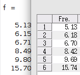
It can be observed that the calculation results are approximate.
References:
[1]曾令贤.用MATLAB计算发动机悬置系统的固有频率和主振型[J].汽车科技,2005(04):27-29.
[2]王星. 电动汽车动力总成悬置系统优化设计[D].合肥工业大学,2015.
[3]薛华,刘志强,刘岩,苏迎.基于Matlab的动力总成悬置系统解耦优化[J].噪声与振动控制,2015,35(02):65-68.
I am a beginner and cannot guarantee the accuracy of calculations. Thanks!
This is a translated copy of my post “使用MATLAB计算动力总成悬置系统固有频率和主振型”, release in April 26, 2022.
Recent Comments